Page 13 of 14
Re: Calculating CFM used from Dyno sheet ?
Posted: Sun May 20, 2018 11:48 pm
by SchmidtMotorWorks
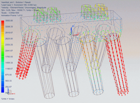
This CFD might be helpful to visualize.
The all receive the exact same signal.
Only one pulse is used and allowed to decay.

Re: Calculating CFM used from Dyno sheet ?
Posted: Sun May 20, 2018 11:55 pm
by SchmidtMotorWorks
Here is how it plays out in a tunnel ram
Re: Calculating CFM used from Dyno sheet ?
Posted: Mon May 21, 2018 1:16 am
by Scotthatch
SchmidtMotorWorks wrote: ↑Sun May 20, 2018 11:48 pm
This CFD might be helpful to visualize.
The all receive the exact same signal.
Only one pulse is used and allowed to decay.
So you agree with how that page works???
It says right on it that even the 2nd harmonic is only good for 10%
So ram is doing the other 90%
Re: Calculating CFM used from Dyno sheet ?
Posted: Mon May 21, 2018 1:54 am
by gruntguru
I think the 10% is the pressure peak above average pressure. So in a "perfect" intake tract you could get 10% supercharge or 110% VE.
"Inertia" and "Wave" tuning are the same thing. Imagine hanging a broom handle vertically from your hand and oscillating your hand up and down - that's inertia. Now imagine the same experiment hanging a long "slinky" spring. At certain frequencies your hand will feel lots of "inertia" and at other frequencies very little "inertia".
Wave tuning harnesses the inertia of the air column. The air column is compressible/springy - not rigid.
Re: Calculating CFM used from Dyno sheet ?
Posted: Mon May 21, 2018 5:47 am
by hoffman900
Scotthatch wrote: ↑Mon May 21, 2018 1:16 am
SchmidtMotorWorks wrote: ↑Sun May 20, 2018 11:48 pm
This CFD might be helpful to visualize.
The all receive the exact same signal.
Only one pulse is used and allowed to decay.
So you agree with how that page works???
It says right on it that even the 2nd harmonic is only good for 10%
So ram is doing the other 90%
Read the thread I linked to. Clint’s first post in the second page:
nitro2 wrote: ↑Tue Nov 15, 2011 1:35 pm
Inertia = 0% Waves = 100%
Lets say we ignore the pulsing effects in the intake at IVO, for simplicity lets say they aren't there. Then at IVO, the inertia when the intake valve starts to open is 0. The inertia in the intake is going to stay at 0 indefinitely, unless acted upon. The action, piston motion (and also residual intake waves but we got rid of them above, and exhaust suction or reversion), causes wave action which in turn causes the intake motion and of course intake inertia increases. Same idea when its all slowing down, wave action happens then the intake motion decreases. Absolutely nothing happens in the intake without wave action, it just sits there stopped. The A/F mixture half way up the runner (or anywhere else) knows absolutely nothing about speeding up from dead stopped until a wave from the cylinder travels up the runner to tell it to get going, and it doesn't know to stop either until a wave tells it to stop. Actually its a series of waves not a simple sinusoidal wave (see further below).
It's important to understand that "wave tuning" as most people think of it is a very specific thing that is primarily related to what happens during overlap rather than during the rest of the cylinder filling period. Only during IVC to IVO do the events in the intake behave like a sinusoidal (or similar) wave and what this wave is doing just before overlap determines to a large degree what happens during overlap. The exhaust wave at overlap plays the other part. So how much effect so called "wave tuning" will have on power really depends largely on how much gain can be made by having a good overlap flush event vs. a not so good overlap flush event.
Wave tuning during the rest of the intake process (i.e. the main cylinder filling process) is a whole different story. The waves are simply an infinite series of tiny wave events all summed up. How they sum up determines what you get for cylinder filling. This is not a sinusoidal event at all. It is also the part of wave tuning that most people don't know too much about.
Re: Calculating CFM used from Dyno sheet ?
Posted: Mon May 21, 2018 7:46 am
by user-23911
Scotthatch wrote: ↑Sun May 20, 2018 11:32 pm
15267463087920.jpg
So am I to assume that the people that posted fully agree with this page on acoustical wave and how it works to make power?
No.
Re: Calculating CFM used from Dyno sheet ?
Posted: Mon May 21, 2018 7:52 am
by user-23911
SchmidtMotorWorks wrote: ↑Sun May 20, 2018 11:48 pm
This CFD might be helpful to visualize.
The all receive the exact same signal.
Only one pulse is used and allowed to decay.
That's not quite right either.
It's an acoustic transmission line.
When there's a change in acoustic impedance, there's a reflection.
When the wave gets to an opening (plenum) the wave (pulse) is inverted and reflected.
When the wave hits a solid object (closed valve) the wave is not inverted but still reflected.
Whet the above sim does NOT show is whether the valve is open or closed.
The principle is exactly the same as used in telecommunications for finding cable faults using a pulse echo tester.
That's how you know both the distance to the fault AND you know whether the fault is an open circuit or a short.
Re: Calculating CFM used from Dyno sheet ?
Posted: Mon May 21, 2018 9:02 am
by swampbuggy
Wow--- i am loving all this, sure glad my simple thread (??????) turned into ALL of this extra data, thanks guy's Mark H

Re: Calculating CFM used from Dyno sheet ?
Posted: Mon May 21, 2018 10:22 am
by Scotthatch
My problem with that page is this
If I take a gen 1 sbc the head has a runner length of 5.5 in and a single plane standard race intake is 6.5 in long
So using that I can figure rpm for the harmonic
2nd = 11000 rpm good for 10%
3rd = 8083 rpm good for 7%
4th = 6166 rpm good for 4%
5th = 4500 rpm good for 1%
So we should see increase in power at those points in the rpm band and if it a sinusoidal wave then at the half way point between them we should see a drop of the same amount from a baseline ..... in essence we should see the wave in the power output of the engine as it helps or hurts the power output yet we don't
15269124405140.jpg
Re: Calculating CFM used from Dyno sheet ?
Posted: Mon May 21, 2018 11:03 am
by DrillDawg
1100 x 141 x .705 \ 6900 = 15.84
If your heads flowed 450 you would peak around 7500rpm, so....
1100 x 141 x .705 \ 7500 = 14.5"
that's why you see extended runners in some single plane intakes
That's using swampbuggy's 516 and 282 duration at .50
Re: Calculating CFM used from Dyno sheet ?
Posted: Mon May 21, 2018 11:15 am
by Scotthatch
DrillDawg wrote: ↑Mon May 21, 2018 11:03 am
1100 x 141 x .705 \ 6900 = 15.84
If your heads flowed 450 you would peak around 7500rpm, so....
1100 x 141 x .705 \ 7500 = 14.5"
that's why you see extended runners in some single plane intakes
That's using swampbuggy's 516 and 282 duration at .50
Not sure I understand what you are saying.......
What formula are you using and do you have more information about the engine
Re: Calculating CFM used from Dyno sheet ?
Posted: Mon May 21, 2018 11:19 am
by DrillDawg
I posted the formulas on page 9 and its the OP engine.
Re: Calculating CFM used from Dyno sheet ?
Posted: Mon May 21, 2018 11:33 am
by Scotthatch
DrillDawg wrote: ↑Fri May 18, 2018 3:09 pm
Intake tract length tuning
2nd pulse
((1100x 1\2intake can duration )x .96)\rpm
3rd pulse, same but use .705 instead of .96
4th pulse, Same but use .538 instead
OK ... not a formula I have seen before so where is it from and what is it based on ?
OP engine?? Code for something?
Re: Calculating CFM used from Dyno sheet ?
Posted: Mon May 21, 2018 11:34 am
by DrillDawg
Lol, original poster, post one on page one. From my 40 year old notebook.
Re: Calculating CFM used from Dyno sheet ?
Posted: Mon May 21, 2018 11:41 am
by Scotthatch
OK ... I have not done car stuff for 10 years as I was to sick and only been here a short time so still getting the lay of the land