Here are three patents distributed over approximately thirty years that discuss many of the points mentioned. It should be noted that part of the original reasoning to move the sensor to the flywheel area was to make it more difficult to modify the system by aftermarket tuners or individuals.
1978 Bendix:
https://patents.google.com/patent/US4235101A/en
2. Description of the Prior Art
A crankshaft position responsive device is an essential element in any ignition timing system, engine cylinder firing system or synchronization system. In many engines, a distributor provides indirect crankshaft information such as engine speed and also distributes the spark to the proper cylinder at an instant when the piston of each cylinder is at a preferred position within its power cycle. Distributors are often driven through a worm gear by a camshaft which in turn is driven by an engine crankshaft. Significant problems do exist in present distributor systems. One source of error arises due to a stackup of tolerances (machining inaccuracies) between the crankshaft-worm gear-distributor cam making precise and repeatable engine synchronization difficult. Dynamic errors are especially evident during periods of acceleration and deceleration during which time imperfections in the gearing such as backlash become more apparent.
A second problem resulting in a constant position offset error arises because crankshaft position is not measured directly but is obtained by measuring the motion of intermediate elements such as a timing gear or vibration damper which can be misaligned relative to the crankshaft. Misalignment may result because of the imprecision in slots, or in keys and keyways that are used to position these intermediate members to the crankshaft.
To eliminate the buildup of mechanical errors due to gearing inaccuracies, systems have employed a sensor mounted proximate to the crankshaft at the front of engine. Such a sensor could be a reluctance sensing device responding to the passage of sense features such as protrusions or holes on a nearby sense wheel which is attached to the crankshaft vibration damper or timing gear
A front mounted crankshaft sensor is susceptible to many sources of error. As an example, it must operate in a hostile exposed environment at the front of the engine. Furthermore, the front mounting, because of its easy accessibility, encourages user tampering. Permitting access to critical ignition components may give the user the opportunity to "fine tune" the performance of his vehicle; however, it is also possible for the user to circumvent the manufacturer's complex ignition timing synchronization which may be necessary to meet legislative standards for minimizing automotive exhaust emissions.
Due to the nature of the automotive market, it is desirable to produce a low cost crankshaft sensing and positioning device which is readily adaptable to most domestic and foreign engines. An advantage of the present invention is that it cooperates with existing engines and engine components so that integration of the crankshaft sensor into the engine is accomplished with a minimum of engine design changes.
It was determined that the rear of most engines are similar. In particular, the bottom rear of many cylinder blocks near the oil pan and within the transmission dust cover affords an accurately machined surface into which a crankshaft sensing element could be mounted with engine design changes, limited for the most part to making provision for sensor fastening holes in the bottom of the cylinder block and minor machining of the crankshaft flange, to the transmission dust cover and flywheel (or flex plate).
Improvements in engine performance such as fuel economy and emissions control require repeatable cycle-to-cycle crankshaft position and speed information. This is accomplished by the present invention. A further advantage of the present invention is that its output or timing signal is not effected by acceleration or deceleration of engine components or by mechanical wear.
It is an object of this invention to provide an improved crankshaft position sensor. It is a further object to accurately measure engine speed and to generate accurate spark timing information. Still a further object of this invention is to inhibit user tampering with the manufacturer specified engine timing while still affording a limited range of adjustability so that the basic ignition timing can be varied in order to compensate for ignition timing changes due to mechanical wear of engine components. It is a further object to monitor crankshaft position directly.
1987 General Motors:
https://patents.google.com/patent/US4782692A/en
In the foregoing systems, if there is a failure in the sensor providing the crankshaft angle signals, the system would be incapable of providing accurate control of fuel or combustion timing to the engine. For example, if one of the teeth spaced around the flywheel for providing the crankshaft angle signals should wear or break off resulting in a loss of the corresponding crankshaft angle signal, a deterioration in the control of fuel and combustion timing would result.
2004 Delphi:
https://patents.google.com/patent/US7021127B2/en
DETAILED DESCRIPTION OF THE INVENTION
As suggested above, even in a steady state condition, an internal combustion (IC) engine may exhibit cyclical speed variations attributable to the operation of its cylinders. The frequency of these speed variation cycles depends on factors such as the number of cylinders in the engine and whether the engine is of a two or a four-cycle type. In two cycle engines, each of the cylinders undergoes respective compression and firing actions during each engine revolution. Hence, there will be as many speed cycles per engine revolution as there are cylinders, and they will be spaced 360/n crank angle degrees (CAD) apart, where n is the number of cylinders. In four cycle engines, one half of the cylinders undergoes respective compression and firing actions during one engine revolution, the other half during the following revolution. In this case there will be n/2 speed cycles per revolution and they will be spaced 720/n CAD apart.
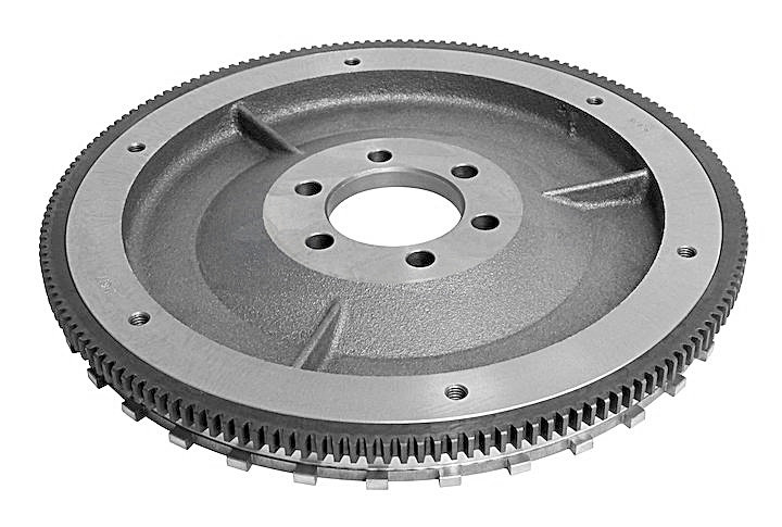
The magnitude of these speed variations may depend on factors such as the compression ratio of the engine, number of cylinders (more specifically, the degree of overlap of compression and firing cycles between the adjacent in firing order cylinders), engine speed and load. For example, in an idling four-cylinder diesel engine the magnitude of speed variations can be as high as 200 RPM, in an idling four-cylinder gasoline engine 60 RPM, and 40 RPM in an 8-cylinder engine. Generally, in a gasoline engine the magnitude of the speed variations will be approximately no more than ±5% of the average engine speed and it will decrease at higher engine speeds. A simple calculation shows that a prior art crankshaft sensor providing 60 pulses/rev with typical accuracy of ±0.5° may introduce a speed error ε=±0.5°/(360°/60)=±8.33%, which would obliterate the ±5% speed variation signal. Aspects of the present invention provide a crankshaft position sensor with a resolution of approximately no less than 5°, and pulse-to-pulse accuracy better than approximately ±0.5%, which for a resolution of 5° corresponds to ±0.025°. Serendipitously, a magnetic target compatible with such sensing resolution and accuracy already exists in every vehicle with an internal combustion engine—the ring gear used by the starter for cranking the engine. Number of teeth in excess of 90, large diameter and machining accuracy required in gear production makes the ring gear suitable as a high quality target wheel.
It is noted that in any practical embodiment, any signal or data indicative of engine crankshaft position information should be obtained directly from the crankshaft of the engine of the vehicle. For example, one may conceptually consider using any of the belt-driven pulleys or other rotating accessories in the vehicle to extract engine crankshaft position information and use it to derive engine speed information, since such pulleys or accessories may be readily accessible. Such information, however, would likely be affected by the fairly complex dynamics of the harmonic balancer and the drive belt, and, in practice, may differ considerably from the actual crank speed of the engine.
~~~~~~~~~~~~~~~~~~~~
My personal FEELING is that serendipity is superseded by intelligent deliberate design.