Reducing the header exhaust port area?

General engine tech -- Drag Racing to Circle Track

Moderator: Team

donforeman
Member
Member
Posts: 163
Joined: Mon Feb 02, 2015 11:04 pm
Location: Medford OR
Contact:

Reducing the header exhaust port area?

Post by donforeman »

I have been reading a lot of the older header building posts and want to try building a smaller diameter primary header. Application 70s is a 1.2L Honda used for vintage racing. Not a super serious effort, but I would like to learn a bit on my way through the reassembly of the car. The engines were about 50hp stock and are not that powerful even with modifications, about 35 hp per cylinder is average even modified. A 1-3/8" 18 gauge tube matches up to the round port almost exactly, but I think for the hp level it still may be too big. I would like to try using a straight section of 1-1/4" 18 gauge tube for the first section off the flange. To properly reduce the area off the header flange, do I make up a taper form on the lathe and just try to force the tube over it with my press and some heat to make the transitions? There is some talk of reductions, but no one really spells out how, other than to say it should not be an abrupt transition.
For period of over 5-6 years, (about 98-2003-4) Cup engines would use a header with a 1.75" od tube off the cylinder head. The funny part is, the area of that tube was approximately 9-10% smaller than the port area at the flange surface! I am talking about championship teams here. Using 1.75" test tubes on flow bench would hurt flow numbers and believe me, if you did not shape the transition from port to tube right, you would lose power! Fun stuff for me and very frustrating to head porters, then and now! I use the fact that the engine wanted the smaller tube to support my efforts to help people understand that most ports are larger than they need to be largely as a result of headers that have always been too large!
Let's not even mention the BBC or the Cleveland Ford exhaust size, good grief. I commonly squeeze the area down on those two monsters up to 23-25%. They need velocity not more flow potential.
Image
Momus
Pro
Pro
Posts: 307
Joined: Tue Aug 13, 2013 8:38 am
Location:

Re: Reducing the header exhaust port area?

Post by Momus »

A turned taper former, some grease and cold pressing will work well for your mild expansion.

I did some work on a EB1 Civic- the first one- though with B16 engines installed.


With a brake upgrade and my drivers limited travel rear suspension it was famous for doing wheels right off the deck stoppies.
donforeman
Member
Member
Posts: 163
Joined: Mon Feb 02, 2015 11:04 pm
Location: Medford OR
Contact:

Re: Reducing the header exhaust port area?

Post by donforeman »

Thank you for the tips!
Nut124
Pro
Pro
Posts: 309
Joined: Wed May 06, 2020 10:44 pm
Location: Michigan, USA

Re: Reducing the header exhaust port area?

Post by Nut124 »

If you are putting in a tapered reducer, a flow restriction, just off the primary flange, does that really work the same as a native smaller port diameter and matching primary?
donforeman
Member
Member
Posts: 163
Joined: Mon Feb 02, 2015 11:04 pm
Location: Medford OR
Contact:

Re: Reducing the header exhaust port area?

Post by donforeman »

There is a very smart person here that goes by the screen name of "Exhausted" If you do a search he mentions it a lot with good results. I spent a few evenings looking at all his posts and other members on the same subject
viewtopic.php?f=15&t=55767 This one is a good start.

His blog is down, but google still has a few pages cached. Of course it would be better to start with a smaller port, but sometimes its not feasible.
https://webcache.googleusercontent.com/ ... ing101.com

The head I took off the car many years ago was horribly hogged and the powerband was horrible. Its not just the header or head problem but it contributed to it. A much milder engine in a similar civic (I owned two at the time) would kick its butt top to bottom rpm wise on track. This time the port faces are much smaller, as cast. Most of the work was done in the chamber and bowl area, but still large ports for the size of the engine and its expected hp. I am not sure if it will work or not, but a few weekends and a few hundred in bends it seems like its worth a shot. I like tig welding and I need more practice anyway. I have a chassis dyno that could be used to compare, if I stop bs'ing on the computer and get it running again one day.
Calypso
Pro
Pro
Posts: 458
Joined: Mon Oct 17, 2005 1:38 pm
Location:

Re: Reducing the header exhaust port area?

Post by Calypso »

If you look at the typical low loss venturi shapes, the contraction can be much more abrupt than the expansion without flow loss. Nicely rounded entry to right size pipe would not lose much and it would flow poorly backwards.
mag2555
Guru
Guru
Posts: 4604
Joined: Sun Sep 18, 2011 11:31 am
Location: Heading for a bang up with Andromeda as we all are.

Re: Reducing the header exhaust port area?

Post by mag2555 »

The key to making better usage of what what be a oversized Exh port starts with the valve!

Since the Exh port is either pressurized or not by the blow down period and the Exh cylcle , in other words it's either on or off for some amount of time that gets reduced as the rpm goes up then the part of the key is to keep it better untilized during times when it's Below the max percentage of being utilized.

A simple back cut can get more flow out of the chamber and into the Exh port during what can be looked at as down time during the start of the blow down period.
You can cut a man's tongue from his mouth, but that does not mean he’s a liar, it just shows that you fear the truth he might speak about you!
donforeman
Member
Member
Posts: 163
Joined: Mon Feb 02, 2015 11:04 pm
Location: Medford OR
Contact:

Re: Reducing the header exhaust port area?

Post by donforeman »

Thank you for all the feedback. I am going to give it a try, if it works great, if not its tig welding practice.
User avatar
MadBill
Guru
Guru
Posts: 15024
Joined: Tue Nov 15, 2005 10:41 am
Location: The Great White North

Re: Reducing the header exhaust port area?

Post by MadBill »

One way to fit 1-1/4" primaries would be to cut say 3" stubs of that diameter and taper the ODs down to near-zero at the head ends with a bench grinder or lathe, then swage/drive them into the (presumably tapered) ports* (heated if need be for ease of conformation), weld the flanges on with the stubs backed out a smidgen to allow easy removal, then butt weld your new 1-1/4" primaries to them. Stepping up to 1-3/8" tubes say 10" out might be beneficial.
Felix, qui potuit rerum cognscere causas.

Happy is he who can discover the cause of things.
donforeman
Member
Member
Posts: 163
Joined: Mon Feb 02, 2015 11:04 pm
Location: Medford OR
Contact:

Re: Reducing the header exhaust port area?

Post by donforeman »

Thank you for the feedback. So up until I started reading here, my choice has been 1-3/8" as it fit the port exit of stock sized heads without restriction. The 1-1/2" primary with hogged heads that were on the car was a dog on track it seem to lack on the lower rpm ranges and not get anything back on top. I think that a straight section of 1-1/4 18g tapered to match the port may work before stepping to the 1-3/8 16g. I don't think I can run it out past about 5 or 6" before having to bend the tube though, so maybe this is not going to work. The problem with the smaller sized tubes is that each eighth in tube size is such a drastic area change percentage and the radius from common sources of bends are very tight. From what the member "Exhausted" was sharing, I think its not just the smaller diameter, but very large diameter bends to go with that choice. So not sure of running the smaller diameter though a tight bend would do. I thought about using pie cuts to make a large diameter radius, but not sure if that would work any better as they are not as smooth as standard bends.
hoffman900
HotPass
HotPass
Posts: 3460
Joined: Sat Feb 23, 2013 5:42 pm
Location:

Re: Reducing the header exhaust port area?

Post by hoffman900 »

Exactly it.

One thing to keep in mind with Calvin’s sizing is that it needs large bend radii, which requires very well done packaging, to make work. You’re not going to do what Calvin does and make it work with a 90 on a 3” bend radius. This is how headers partly end up being so large anyway because the packaging sucks (cost, lack of talent, etc) and the tubes need to be larger so they can flow enough around a tight bend. Calvin basically started building headers that preserved flow really well and found he could reduce the size of everything as a consequence, which in turn has its own benefits.

A talented fabricator can make his designs work, but I haven’t seen many who fully understand it outside of people do high end pro stuff (NASCAR, WSBK/MotoGP, etc) and at that point, they are all about the same price wise.
-Bob
MetricMuscle
Member
Member
Posts: 62
Joined: Thu Jan 04, 2018 6:59 pm
Location:

Re: Reducing the header exhaust port area?

Post by MetricMuscle »

I've seen folks fill in intake and exhaust ports and reshape etc. but what about using a divider type design to partition off part of the exhaust port that is too big. Like if you had around 2" ID exhaust port and used a smaller diameter tube, say 1 5/8", formed into a "D" shape which was located at the top of the port and the flat part of the "D" protruded into the port so as to lessen the area. Just the top area of the exhaust port was open to exhaust flow. This is assuming that the shape of the port would allow this.

The new Nissan Titan 5.6 liter gasoline engine sports "YUGE" 2" exhaust ports. The only thing I've seen about why is that it was done to improve exhaust manifold life, or something.

Image
donforeman
Member
Member
Posts: 163
Joined: Mon Feb 02, 2015 11:04 pm
Location: Medford OR
Contact:

Re: Reducing the header exhaust port area?

Post by donforeman »

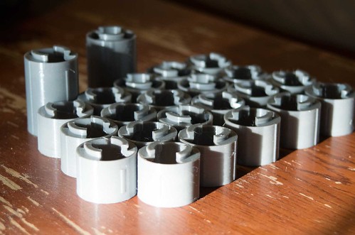
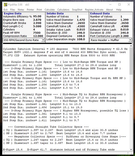
Just an update, The advice I received above put it in perspective so I stopped thinking about shrinking the port outlet. I had 1-3/8" tube 16g on a 3" radius to work with and even that was hard to find as most 1-3/8 u bends are 2.5" radius or smaller. The packaging is tough even with that. This project has been sitting in my garage for way too long (decades), and a lot of it is I repeatedly over complicate the next step in project, when I should just get it done and put it back on the track even if its not perfect. So a simple 4-1 is where I need to start. Its my first complete header build so I printed out some rough plastic parts on a cheap ender 3 printer to help visualize where I am going. For the collector I also printed out a plastic jig to hold the tube at mostly the right angle to make the cuts. I am still not sure what direction the tubes will run, but realized I need to have a collector to point things at even in plastic, so stopped playing with header legos and started cutting... then I ran out of argon so progress is stopped for the weekend. I am using pipemax from the 2016 group buy here, but some things have to be changed as its not as simple as it looks on the computer screen. If I run the pipes down to the passenger side the primary tubes end up shorter, close to the 19" and 4th harmonic listed in pipemax but the pipe lengths look to be kept closer to equal. If I run them into the fender area the lengths vary a lot more and the tubes could end up really long if I size the shortest tube correctly.

For the collector if I read it right, Pipemax recommends a choke of 1-1/4 to 1-1/2, but premade cones start at 1-1/2? So the smaller options are not available unless I learn how to make my own cone some way. Right now the collector outlet is 1-3/8" but its not to hard to redo what I have done so far. The engines are not that powerful, around 140hp or 35hp per cylinder is about max even when modified, so I am thinking 1-3/8" choke point in the 4-1 collector may be as large as I want to try. I just figured I would post up the plan and see if any more experienced people had feedback or suggestions.

Image

Image

Image

Image

Image

Image

Image
brentry
Member
Member
Posts: 128
Joined: Fri Aug 16, 2013 5:56 pm
Location:

Re: Reducing the header exhaust port area?

Post by brentry »

Quote
Unless I learn how to make my own cone some way.

Slip roller, cone program, some sheet metal.
Some bar stock turned into a big cone used for pounding
Ends into round shape. Steel rod with ball bearing welded to end to pound radius's into shape. Disc Sander to sand ends..
Torch or tig welder..
And alot of time learning .
Make it straight or a taper ,any size or radius you want
Post Reply