Page 2 of 3
Re: 243 LS SSR...Stumped.
Posted: Tue Jun 08, 2021 2:53 pm
by SpeierRacingHeads
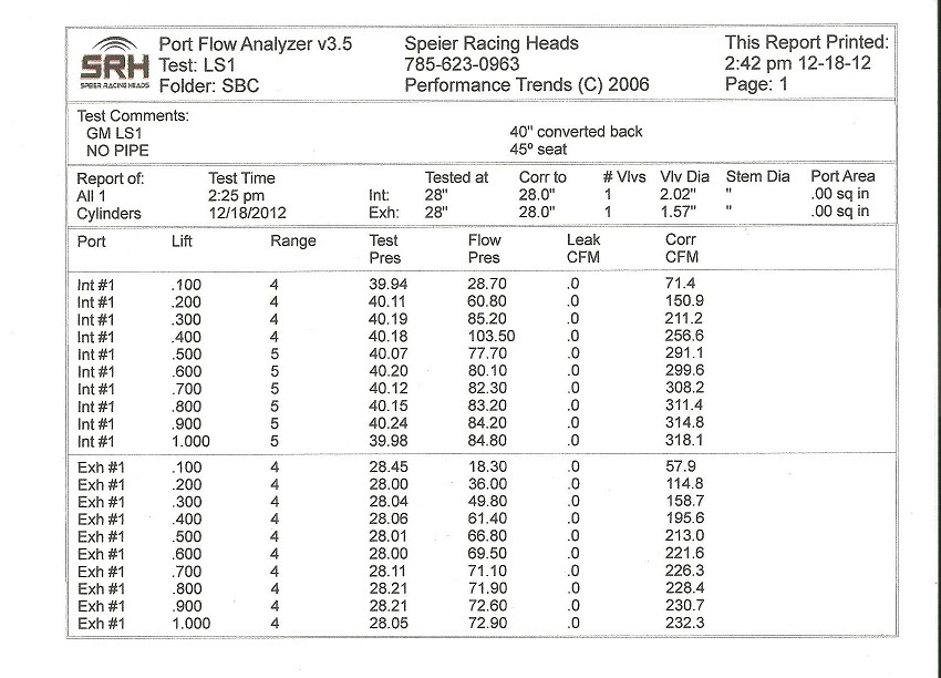
Here is my 243 flow curve. Notice I flowed at 40" and the numbers are converted back to 28"..
Re: 243 LS SSR...Stumped.
Posted: Tue Jun 08, 2021 4:22 pm
by fasteach
Gentlemen, thank you for the interest and helpful replies. Much appreciated!
Mag2555 Thank you for the photo.
If i remember correctly, that was a Mamo Motorsports CNC head with a 2.055 intake. I followed that thread with interest. Did you ever get the head poured for cc?
Chad; your work, as always, is impressive. I'm picking up what you're putting down.
Currently my FP1 flowperformance bench struggles to keep 28" with this head, and i will have to get off my butt & install the Ametek 115923s i have under my workbench...those old surplus center motors are on their last legs and i'm out of spares.
Currently my flows are as follows:
.100 .200 .300 .400 .500 .550 .600 .700 .800
69....150..210..253..282.290..284..270..272
If I can answer any questions, please ask. I have measurements, pitot data & other relevant criteria to share.
Not trying to set any records, just trying to help a student with a project and learn something for myself along the way.
Duke
Re: 243 LS SSR...Stumped.
Posted: Tue Jun 08, 2021 6:01 pm
by PRH
Finish the turn with 80 grit linishing tape pulled back & forth over it.
steve cowan wrote: ↑Tue Jun 08, 2021 1:31 pm
What Tony is describing is NOT the riblet,
It's basically smoothing the apex in the direction of flow.
Speeds are fast and boundary layer thin and fuel is trying to turn.
It's not a cfm gain,more helping with stability.
It's a cool speed secret.
My interpretation of Dons description of the riblet is the same as what Tony described there.
Where is the fundamental difference?
Re: 243 LS SSR...Stumped.
Posted: Tue Jun 08, 2021 7:50 pm
by steve cowan
My take on riblets are small channels, my interpretation is what I described, hopefully TK can confirm as I could be wrong....
A picture is worth a thousand words.
Re: 243 LS SSR...Stumped.
Posted: Tue Jun 08, 2021 8:25 pm
by fasteach
Steve;
I believe i read the riblet technique in Don's 740hp nascar book that everyone bought back in the day.
seems it was the top of the right side page. Described in detail the grit, direction of motion, and theory.
The theory was that the grooves left from the coarse grit applied extra surface area to a SSR surface, and all that would allow.
I gifted the book to a friend or i'd quote the page.
Re: 243 LS SSR...Stumped.
Posted: Tue Jun 08, 2021 9:33 pm
by KnightEngines
I just meant to polish the turn in the direction of flow.
Helps stability.
Re: 243 LS SSR...Stumped.
Posted: Tue Jun 08, 2021 10:59 pm
by BradH
Don T said to use 36 or 40 grit on the SSR in the direction of flow in order to leave small grooves in the surface, not polish it smooth & shiny.
Google "riblet fluid flow" and you'll see multiple links to research papers on the subject going back decades. Ignore the links where the topic is "pork or beef", though, unless you're planning a cookout.

Re: 243 LS SSR...Stumped.
Posted: Wed Jun 09, 2021 2:48 am
by steve cowan
20210609_164116.jpg
20210609_163941.jpg
20210609_163844.jpg
20210609_163543.jpg
I was fortunate enough that Don sent me all this plus more back in 2011.
Re: 243 LS SSR...Stumped.
Posted: Wed Jun 09, 2021 6:50 am
by mag2555
The question needs to asked how much power does this student need to make, since 290 cfm is good for 600 hp.
Whatever you do in reaching for greater higher lift flow you do not want to degrade that 150 cfm @ .200” lift !
That is a nice fat number and will help to keep the max HP made from nosing over fast and should always be kept in mind!
Re: 243 LS SSR...Stumped.
Posted: Wed Jun 09, 2021 9:44 am
by BradH
BradH wrote: ↑Tue Jun 08, 2021 10:59 pm
Don T said to use 36 or 40 grit on the SSR in the direction of flow in order to leave small grooves in the surface, not polish it smooth & shiny.
Google "riblet fluid flow" and you'll see multiple links to research papers on the subject going back decades. Ignore the links where the topic is "pork or beef", though, unless you're planning a cookout.
Looks like DT said to use 50 grit; regardless the intent is not for the surface to be "polished", but "striated".
Re: 243 LS SSR...Stumped.
Posted: Wed Jun 09, 2021 6:10 pm
by PRH
Still sounds to me like what TK was suggesting and what DT was instructing are fundamentally the same thing.
A9BD8EF5-70A3-4956-9DCE-32EB0675CF2E.png
Re: 243 LS SSR...Stumped.
Posted: Wed Jun 09, 2021 9:33 pm
by BradH
FWIW, here's a short turn on my "crash test dummy" head that I just used 50 grit on. Ya' probably need to click on the image to display it more clearly.
20210609_211753.jpg
Re: 243 LS SSR...Stumped.
Posted: Wed Jun 09, 2021 9:43 pm
by steve cowan
PRH wrote: ↑Wed Jun 09, 2021 6:10 pm
Still sounds to me like what TK was suggesting and what DT was instructing are fundamentally the same thing.
A9BD8EF5-70A3-4956-9DCE-32EB0675CF2E.png
Just to keep you happy -
Let's just say you are fundamentally correct as always.
Re: 243 LS SSR...Stumped.
Posted: Wed Jun 09, 2021 10:12 pm
by fasteach
Update;
Laid the SSR back some and moved the crest towards the gasket a touch as instructed, with positive results.
.100 .200 .300 .400 .500 .550 .600 .700 .800
69....147..209..252..281..290..290..272..278
Not fixed...but progress, and only 2-3cc of metal removal.
Thank you for all the helpful advice and assistance so far.
Re: 243 LS SSR...Stumped.
Posted: Thu Jun 10, 2021 6:21 am
by mag2555
Could you please post a photo of the center of your short turn arc formed with a lenght of solder?
Two dimensional pictures of something that is 3 dimensional with compound angles are useless!
Another way to control short turn velocity is also by manipulation of the short turn, but at the transition of the bottom cut to the short turn.
After the end of the bottom bottom cut in the bowl grind or cut in a straight section.
Start off about 1/16" tall and then perform a flow test.
The critical detail about forming this straight section is that it must be parallel with the valve inclination angle of the head.
The outside port wall run also needs to meet the rear bowl wall with a near as you can get 90 degree angle