Flathead Transition Area - What & where is it?
Moderator: Team
Re: Flathead Transition Area - What & where is it?
Thanks for the pictures. No one has asked what are your intentions with this hybrid/performance Jeep engine?? Have you done any flow bench testing?? Also it would be interesting to see Dyno figures with the stock head
vs the head you fabricated. Also using stock bore and stroke a 100 head cc, 0 deck and .035 thick head gasket I came up with 6.9/1 compression.
Pete can you give any information on time and location where a tear down might take place. I am sure I can arrange my schedule to be there.
vs the head you fabricated. Also using stock bore and stroke a 100 head cc, 0 deck and .035 thick head gasket I came up with 6.9/1 compression.
Pete can you give any information on time and location where a tear down might take place. I am sure I can arrange my schedule to be there.
Re: Flathead Transition Area - What & where is it?
Almost any race track where money is involved in winning the A main.
Also at any LSR event.
Re: Flathead Transition Area - What & where is it?
It's my understanding that a thicker boundary layer, created by a rougher surface, is what results in better wet flow. If, by wet flow, you mean the movement of condensed fuel on the port walls. I believe the amount of condensation is essentially the same, regardless of surface roughness, but with a rougher surface, the condensation is transported along the walls with out having the opportunity to form observable beads - just a thought based on my understanding if fluid dynamics.n2omike wrote: ↑Tue Oct 26, 2021 10:26 amMy thoughts... A burr finish will have better wet flow, but create a thicker boundary layer.Erland Cox wrote: ↑Fri Oct 22, 2021 9:49 am And I have tested burr finish versus smoother finish on a dyno and there is a transient difference.
Wall wetting is much less with a burr finish.
https://www.highpowermedia.com/Archive/ ... tau-factor
http://www.megamanual.com/ms2/xtau.htm
Erland
If you need all the area you can possibly get, a burr finish may not be the best move. If there is plenty of area, doing a burr finish where fuel is likely to pool/collect (walls in the fuel's direct path) may have some benefit.
http://www.sleigh-munoz.co.uk/fluidsnot ... 04/T2.html
In any case, changing the intake surface finish is now on the list!
Re: Flathead Transition Area - What & where is it?
FWIW, flow testing a flathead is not easily done on a conventional OHV flow bench.
There may be other methods, but the only reliable one I've seen required building a stand to hold the block in place, using a piston with the top cut out and O-rings in place of the piston rings, a thick-walled hose connected to the orfice and pulling vacuum out the bottom. To get an accurate reading requires the carb and intake bolted to the block.
FWIW, in search of an easier method tried pulling the vacuum out the top of the intake, but the reverse flow gave completely different results than did pulling out the bottom.
Another attempt at an easier setup similar to a leakdown tester and reading air pressure depression through the intake; again, different result than pulling vacuum out the bottom.
Relying on three different methods to indicate increased flow, which would make the most power was never compared tested and proven.
FWIW, in the early '50s, before he built his flow bench from a GMC blower powered by a 50hp 3-phase electric motor, Smokey Yunick was racing Hudson Hornet 308" flathead sixes. To improve flow in areas unreachable to hand porting, he used the empirical method, connecting a grout pump to the carb pad of the intake and pumping concrete slurry through the manifold and the block, the forerunner of ExtrudeHone.
jack vines
Jack Vines
Studebaker-Packard V8 Limited
Obsolete Engineering
Studebaker-Packard V8 Limited
Obsolete Engineering
Re: Flathead Transition Area - What & where is it?
The bore, at 3.391", is 0.080" over the standard 3-5/16 inches; the 4.8" stroke is 0.425" longer the the standard 4.375 inches' the head gasket thickness is 0.032 inch; the head gasket area is 15 square inches, the deck clearance 0.012" (I consider below the block deck positive because it adds to the compressed area). Those numbers should work out to 7.5.jed wrote: ↑Tue Oct 26, 2021 2:10 pm Thanks for the pictures. No one has asked what are your intentions with this hybrid/performance Jeep engine?? Have you done any flow bench testing?? Also it would be interesting to see Dyno figures with the stock head
vs the head you fabricated. Also using stock bore and stroke a 100 head cc, 0 deck and .035 thick head gasket I came up with 6.9/1 compression.
Pete can you give any information on time and location where a tear down might take place. I am sure I can arrange my schedule to be there.
Here is a link to more engine information: https://drive.google.com/file/d/1jzVxHF ... sp=sharing
It has been on a chassis dyno just one time. We stopped the pulls at 4100 rpm because torque started falling off rapidly at 3200 rpm and the HP was peaking. The goal is 200 hp at the rear wheels and we were not doing to get there for a variety of reasons so I decided to stop the testing. One reason was supercharger belt slippage limited boost to 4.8 psig. The Paxtons, as setup, are good for another 3 to 4 psi. Here is a chart that show the belt slip effect (in a perfect world boost should follow the upper black curve: https://drive.google.com/file/d/1xNEjTD ... sp=sharing
Here it is on the dyno: https://www.youtube.com/watch?v=MK9oFsp35yk I was scared s**tless - the dyno operator strapped it down, gave me a of couple of instructions, handed me the controller, and said good luck. The turner was logged into my laptop remotely. Next time won't be as bad.
Another significant reason for stopping the pulls at 4100 rpm was fear of detonation. Due to the Edmonds head condition I would not let the tuner add more than 13 degrees of total timing. Call me chicken but the engine lived to run another day. The belt slip issue is resolved and the new head is what I consider to be detonation resistant so I am now willing to add more timing. I have also added a knock sensor that seems to be quite dependable at remove timing from any cylinder before things turn into a bad day. I can also energize the so far not used water-methanol system to cool down the intake air.
Because everyone likes to see bigger numbers I converted rwhp to bhp by adding in drive train losses. To do that, I used engine and chassis dyno results from someone's freshly rebuilt stock Super Hurricane engine. I call it the Waldman data, after the guy that did the testing.
Waldman's engine dyno results tracked remarkably close to the factory published data. After installing the engine in his Utility Wagon, configure as mine is with a manual transmission and a Spicer Model 18 transfer case, he put it on a chassis dyno. Those results show a 30% horsepower reduction.
Based on that test, I applied a 30% loss to my chassis dyno results.
This image shows the dyno results: https://drive.google.com/file/d/1KAcNBP ... sp=sharing
This chart is busy but has a lot of information. The upper curve (engine goal) was made at the beginning of the engine design process - it was the goal. Other than the real world torque curve being much flatter at low rpm, it is still a valid goal. The Waldman data is on there and the factory performance data is there too.
This chart shows the dyno data increased by 30% (drivetrain loss) and plotted next to the goal performance curves.
https://drive.google.com/file/d/1Fx9fJA ... sp=sharing
I haven't done flow testing due to how not easy it is and no, no one has asked about my intentions with this hybrid/performance Jeep engine."
And if still interested, one of favorites - first time to 4800 rpm, 0- 60 mph in about 12.3 seconds.
https://www.youtube.com/watch?v=RtkRVhDYCRk
Re: Flathead Transition Area - What & where is it?
Flow testing would be nice but as you said, "not easy." Since the engine is supercharges, would it be valid to pump pressurized air the intake to simulate forced induction?PackardV8 wrote: ↑Tue Oct 26, 2021 3:49 pmFWIW, flow testing a flathead is not easily done on a conventional OHV flow bench.
FWIW, in the early '50s, before he built his flow bench from a GMC blower powered by a 50hp 3-phase electric motor, Smokey Yunick was racing Hudson Hornet 308" flathead sixes. To improve flow in areas unreachable to hand porting, he used the empirical method, connecting a grout pump to the carb pad of the intake and pumping concrete slurry through the manifold and the block, the forerunner of ExtrudeHone.
jack vines
Pumping concrete slurry through the manifold and block is what I call innovative!
I should have started with a Hudson 308 but I am using Hudson lifters.
Re: Flathead Transition Area - What & where is it?
I saw where you had bushed the lifter bores. What is the lifter body diameter and the foot diameter??
-
Ken_Parkman
- Expert

- Posts: 661
- Joined: Sun Jan 02, 2005 11:30 pm
- Location: Ontario, Canada
Re: Flathead Transition Area - What & where is it?
I would think flowing the system in right direction with representative boundary conditions as much as possible, then you can learn from there. It would be usable for delta's, but the whole thing is so different comparing it to other data would be very challenging. In any case it is difficult to simulate engine operating conditions on the intake, and impossible on the exhaust, so you have to keep that in mind. Just like conventional CFD does not work for 2 phase flow; all analysis has its limitations. Still can teach you a lot though.
So a large pipe somehow sealed to the bore from below as per Jack, or use the bench on exhaust direction and blow into the intake. You would be able to get a flow rate for a given delta P in either case, just keep the delta P high enough to maintain turbulent flow. There can be some serious differences with flow separation depending on the flow direction, so it should be in the correct direction.
BTW - I just scored a Hurricane F head, and am going to stick it on the bench just for giggles. A bit of a challenge with the combustion chamber not much related to the bore. And to get a small enough bore to seal correctly. Looks like the tiny 3.344" bore from the Tornado is "close enough" for the even smaller 3.125" Hurricane. It too will be fun to interpret the data.
Re: Flathead Transition Area - What & where is it?
jed wrote: ↑Tue Oct 26, 2021 7:19 pm I saw where you had bushed the lifter bores. What is the lifter body diameter and the foot diameter??
[/quote
The Continental lifter body is 3/4" with a 1" head (maybe "foot " as you call it is the correct term?) diameter.
The Continental lifter bores are bushed to accept the Hudson 11/16" lifter body. The Hudson lifter has a 1.230" diameter head and 1.128" of that is swept by the cam lobe. If I were to install a cam with more lift different lifters with larger heads would need to be installed in order to keep keep the cam lobe on the lifter.
Please let me know if it is a head or a foot.
Re: Flathead Transition Area - What & where is it?
I don't follow what this means or is referring to. I take my vehicle somewhere and someone takes the engine apart? Why?
Re: Flathead Transition Area - What & where is it?
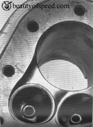
There's also a floor in the transition area.
Are the valve seats generally so high in the deck that there's minimal to gain by working the floor/deck?
I would have thought somehow that one would go with the other. I know the compression issues, but all I've seen is different head work.
The top of the bore is a shortside right, and we have meat to work on till the top ring.
Magnús Aðalvíkingur Finnbjörnsson
Re: Flathead Transition Area - What & where is it?
As was mentioned earlier, relieving the block has fallen out of favor among some flathead experts. Once the shortside turn reaches 180-degrees it becomes different than the OHV shortside.miniv8 wrote: ↑Wed Oct 27, 2021 7:42 pm There's also a floor in the transition area.
Are the valve seats generally so high in the deck that there's minimal to gain by working the floor/deck?
I would have thought somehow that one would go with the other. I know the compression issues, but all I've seen is different head work.
The top of the bore is a shortside right, and we have meat to work on till the top ring.
Jack Vines
Studebaker-Packard V8 Limited
Obsolete Engineering
Studebaker-Packard V8 Limited
Obsolete Engineering
Re: Flathead Transition Area - What & where is it?
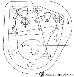
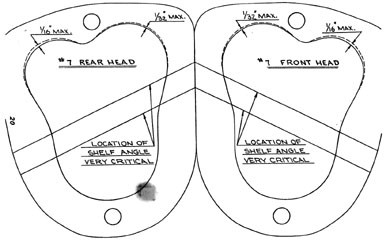
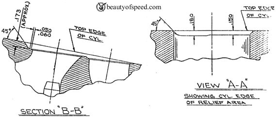
I brought this up, on the first page. 3/16-1/4R could be done with most pistons, I later said it could be as much as 3/8R but, in that case, the top ring, would need to be at least .400 down. That sounds like a lot but, the Ford FE pistons in at least '58 were that far down.frnkeore wrote: ↑Wed Oct 20, 2021 2:37 am I am not a advocate of relieving blocks! But, I think what should be done, is to, radius the top of the cylinder, in the transfer area, to 3/16 - 1/4"R , depending on how far down the top ring is.
Rather than cause turbulence going over a sharp edge, the radius, could promote tumble.
Something else, if there is enough space, between valves, I think there should be a divider, extending down to the block, between valves, creating a individual "port", into the cylinder and the shape of that port could be tuned for increased flow and and increase mass, to increase compression. It would also help with managing overlap flow.
You loose a little compression doing it that way but, I think the gains would be well worth it.
I also think the transfer area should be asymmetrical based on the flow needs. Your port and valve size, based on being a L head is less than 180 cfm. I'm correlating this with Ford FH, flow bench result I have and it was 150 cfm, ported.
I think, as I said before, that the ports should be partitioned, as much as possible and biased to the intake and the transfer proportion (reduced) to the ex side, to raise compression.
There are a lot of air flow shapes that could be explored.
Re: Flathead Transition Area - What & where is it?
“A main” I am pretty sure refers to circle track racing. Usually there are 2/4 heat races. There are maybe 8/11 cars in each heat. Where you place in the heat puts you either in the B feature race or the faster cars in the A main or feature race. I didn't know they started tearing down engines of winners of the A main. They used to only P&G the engines to get a cubic inch number.
“LSR” stands for land speed record. Engine tear downs are a must in LSR because your setting a “international” recognized LSR.
Thanks for the detailed information and videos. Very enjoyable and informative. I will have to say you can be very proud of yourself in the completion of this project. I know I am proud of you and thank you for sharing/openly your project.


