Barney Navarro was a pretty sharp dude.
"In the Hey-Day of Ford V8 Flathead Hot Rodding, four out of five Dry Lakes Records were held with Navarro heads and manifolds."
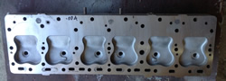
This is reportedly what he thought a flathead Ford combustion chamber should look like, at one time.
https://i1.wp.com/handhflatheads.com/wp ... C800&ssl=1
Flathead Transition Area - What & where is it?
Moderator: Team
-
Dan Timberlake
- Guru

- Posts: 1747
- Joined: Tue Jan 15, 2013 8:10 pm
- Location:

Re: Flathead Transition Area - What & where is it?
Are there any pictures or diagrams of the valve/block side of the combustion chamber??

Re: Flathead Transition Area - What & where is it?
I can'tsay for sure from the photos, but pretty sure those heads are intended to be used with domed pistons. If so, do you know the dome radius and how close the dome comes to the head at TDC?Dan Timberlake wrote: ↑Sun Oct 24, 2021 11:25 am This is reportedly what he thought a flathead Ford combustion chamber should look like, at one time.
Re: Flathead Transition Area - What & where is it?
Combustion chambers with head gasket
https://drive.google.com/file/d/1CvK9gT ... p=drivesdk
Checking machined chamber shape and volume with go no-go gauge blocks
https://youtu.be/LdMUUyAp6tU
-
Dan Timberlake
- Guru
- Posts: 1747
- Joined: Tue Jan 15, 2013 8:10 pm
- Location:
Re: Flathead Transition Area - What & where is it?
I think some web page or article said Mr Navarro used tooling he already had for chrysler hemi to make the domed flat head pistons. And he chose to hemi the pistons and heads because Miller or Axtell or somebody and he were talking about the extra surface area and heat transfer of a cylindrical pop-up, plus a bunch of extra crevice volume.wkuran wrote: ↑Sun Oct 24, 2021 8:55 pmI can'tsay for sure from the photos, but pretty sure those heads are intended to be used with domed pistons. If so, do you know the dome radius and how close the dome comes to the head at TDC?Dan Timberlake wrote: ↑Sun Oct 24, 2021 11:25 am This is reportedly what he thought a flathead Ford combustion chamber should look like, at one time.
Re: Flathead Transition Area - What & where is it?
Wkuhan I am assuming this is your head for the Jeep. Looks good. How did you arrive at the chamber design??
The chamber looks deep and large. What do you think the compression will be??
The chamber looks deep and large. What do you think the compression will be??
Re: Flathead Transition Area - What & where is it?
Thanks. Yes, it is for my Willys
The chamberbers or 0.661" deep, 100 cc and give a 7.5:1 compression ratio.
Good question about the chamber design. It evolved from looking at pictures of flathead chambers, asking questions, reading engine design texts, making models and doing analyses.
With 0.694" deep chambers when used with a 0.032" head gasket I thick it is deeper than most - that makes it easier (less pressure drop) to turn the corner from the valves towards the cylinder bore. Better but probably not measurable.
All chambers are the same shape (some are mirror images] and all curves are tangent - better but not measurable.
The entrance to the cylinder uses 1.5" radius that is tangent to the deck - another feature I consider good but not measurable.
The spark plug is located in the geometric center of the effective chamber (different from the actual or physical chamber). This is intended to reduce detonation.
Quench area is 37% of the piston area and the quenanalysis. Is 0.041" which should create good turbulence and promote a fast burn.
Now that I understand the process of making a head, the next one will a much different looking chamber. This one challenged my modeling and machining skills.
Re: Flathead Transition Area - What & where is it?
I did some looking and found a picture of a stock head/chamber. Yours some what resembles
The stock chamber. https://shop.willysamerica.com/v/vspfil ... r_head.jpg
What plans do you have for the valve and block transition area??
Also what plans do you have for the port??
The stock chamber. https://shop.willysamerica.com/v/vspfil ... r_head.jpg
What plans do you have for the valve and block transition area??
Also what plans do you have for the port??
Re: Flathead Transition Area - What & where is it?
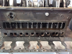
https://shop.willysamerica.com/v/vspfil ... _block.jpg
https://shop.willysamerica.com/v/vspfil ... spring.jpg
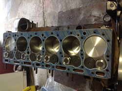
A couple of photo’s of the block and head
https://shop.willysamerica.com/v/vspfil ... spring.jpg
A couple of photo’s of the block and head
Re: Flathead Transition Area - What & where is it?
Flat head knowledge comes at a big expense of time an money. Anything that works you will probably not hear about.

Re: Flathead Transition Area - What & where is it?
A good way to learn is be at tear down after something impressive has happened.
Re: Flathead Transition Area - What & where is it?
I suspect there is knowledge out there that is not being shared but I have nothing to protect and am willing to share everything I learn. However, I can only talk about what works, or doesn't work, as it relates to my engine. I don't have enough experience to tell someone that what works on my engine will work with a different engine, even another Continental.
Yes, expensive! I struggle with what something costs. At one point, I was thinking the foundry cost was expensive but that turned out to be small fraction of the project cost when adding the cost of a 3-axis CNC mill. So did the head cost $$$ or $$$$$$$$$?
Re: Flathead Transition Area - What & where is it?
I agree but impressive = expensive. I'm not sure if I have it in me to set up another block. But, if I did, I have al list of things that I would do differently. I don't think of it as having made mistakes, but as I learn more, I look back at decisions and wonder what was I thinking! It's a process.
Re: Flathead Transition Area - What & where is it?
The most obvious difference from the OEM head is the chamber roof height. Modified valve lift is 0.410" the OEM valve lift is 0.284 inch.jed wrote: ↑Mon Oct 25, 2021 10:58 pm I did some looking and found a picture of a stock head/chamber. Yours some what resembles
The stock chamber. https://shop.willysamerica.com/v/vspfil ... r_head.jpg
What plans do you have for the valve and block transition area??
Also what plans do you have for the port??
I'm not sure what you mean, or are referring to, by the "valve and block transition area." If that is the same as the transfer area then you hit on the original intention of this thread: Where is the transfer/transition area? How is it measured, How big should it be and why?
Here are a couple of photos that show the port and bowl work. At 1.61 square inches (1" x 1.61") the intake ports are about 10% larger than the OEM port (about 1/32" of material was removed). To get another 10% would require removing 1/16" more material from the port. It is on the list. The bowls were worked to a point at which they "looked good." Not very scientific but there was nothing to refer to so the porter used his flathead Ford experience.
https://drive.google.com/file/d/1VvLwSL ... sp=sharing
https://drive.google.com/file/d/1RbHULa ... sp=sharing
Re: Flathead Transition Area - What & where is it?
My thoughts... A burr finish will have better wet flow, but create a thicker boundary layer.Erland Cox wrote: ↑Fri Oct 22, 2021 9:49 am And I have tested burr finish versus smoother finish on a dyno and there is a transient difference.
Wall wetting is much less with a burr finish.
https://www.highpowermedia.com/Archive/ ... tau-factor
http://www.megamanual.com/ms2/xtau.htm
Erland
If you need all the area you can possibly get, a burr finish may not be the best move. If there is plenty of area, doing a burr finish where fuel is likely to pool/collect (walls in the fuel's direct path) may have some benefit.