
Branch and H-D insist that there is substantial flow above the valve at full lift.
How much of this depends on the "cup" behind the valve (away from the bore? IDK.
Flathead Transition Area - What & where is it?
Moderator: Team
Re: Flathead Transition Area - What & where is it?
Agree, and they had real flow bench and dyno data.
OTOH, I know one of the top flathead A/T builders who puts his pistons within .020" and valves within .010" of the head and they are top performers.
Jack Vines
Studebaker-Packard V8 Limited
Obsolete Engineering
Studebaker-Packard V8 Limited
Obsolete Engineering

Re: Flathead Transition Area - What & where is it?
H-D is Harley Davidson but what or who is Branch. Any idea how or where I can go to read about their work?
This is interesting but I would still like to understand the transfer area. Where it is, size, how to measure, etc.
Re: Flathead Transition Area - What & where is it?
Jerry Branch (Branch Flowmetrics in Cali) was perhaps the most famous and successful KR tuner, but not a rider or H-D employee (the racing dep't. was Dick O'Brien, Clyde Denzer, and later Peter Zylstra, with a tiny budget). Very nice guy on the phone, his KR history dates to 1957.
His interview with Gordon Jennings (Cycle World June 1965) was what first interested me in the H-D 45" flathead engines, although I only bought one in 1968.
Earlier work by Tom Sifton started relieving and pop-up pistons in the late 1930s.
W/r/t transfer area: I think you're trying to fix something that has exhibited no bad symptoms. A boosted engine is even harder to diagnose. One of the successful boosted cylinder heads (Toyota 2JZ) is nearly identical in design and dimensions to several other L6 types that produce far less power. Toyota does not know why.


Re: Flathead Transition Area - What & where is it?
First, you could measure the transfer area, with modeling clay or silicon.
With the clay, you place a approx amount in the chamber, with the spark plug installed, slowly rotate until the piston stops, pull the plug and continue, to TDC. I've not done this, the clay maybe to stiff to do it, you might need a more pliable media, that will hold it's shape. Thinking about it, you might be able to use Plaster of Paris instead and let it set, used like silicon below.
For silicon, they make one specifically for casting. Level the head, rotate to TDC and pour.
That will give you the exact shape your dealing with. To convert the transfer to Cu In, you cut out what you decide is the transfer area, then weight it. Fine the weight of your media, in Cu In or CC and divide that into your weight and you get volume.
Regarding the valve position, fluids, follow the path of least resistance. There would be less resistance, to forward flow, with a higher lift, than flowing part of that air, over the valve. The closer the valve is to the head, the more blockage it would have to flow, over the valve and promote flow, under the valve. Also, the flow over the valve, going forward, is more turbulent and slower, than flow under the valve.
Direct acting tappets, are limited in lift so, you might need to increase curtain area, too.
Re: Flathead Transition Area - What & where is it?
I have a 3D model of the cylinder head and block so have a clear understanding of their geometry. With the model, I can measure lengths, areas and volume accurately. That is not the issue.
I am beginning to conclude that there is a transfer area, but there is little to no understanding of where it its, how to measure it, how big it should be and why. I am not trying to be an a-hole - I just want to understand and hopefully apply other's experience to a cylinder head design.
Re: Flathead Transition Area - What & where is it?
Thanks for the information. Jerry Branch has done some amazing work. I read some interesting discussions about his hand ported heads versus CNC ported heads. My experience says that a CNC toolpath will be more consistent, but due to casting tolerances, it is impossible to have a single tool path that works for all heads. It would be necessary to 3D scan and create a model of the head, from which a toolpath can be developed. Possible, but time consuming and expensive. I believe an experienced hand porter will get better results. The problem, is that there is most likely getting to be fewer and fewer people that want to invest the time into learning and doing hand work when CNC will get you close.panic wrote: ↑Wed Oct 20, 2021 10:57 pm Jerry Branch (Branch Flowmetrics in Cali) was perhaps the most famous and successful KR tuner, but not a rider or H-D employee (the racing dep't. was Dick O'Brien, Clyde Denzer, and later Peter Zylstra, with a tiny budget). Very nice guy on the phone, his KR history dates to 1957.
His interview with Gordon Jennings (Cycle World June 1965) was what first interested me in the H-D 45" flathead engines, although I only bought one in 1968.
Earlier work by Tom Sifton started relieving and pop-up pistons in the late 1930s.
W/r/t transfer area: I think you're trying to fix something that has exhibited no bad symptoms. A boosted engine is even harder to diagnose. One of the successful boosted cylinder heads (Toyota 2JZ) is nearly identical in design and dimensions to several other L6 types that produce far less power. Toyota does not know why.
Another thing of interest was the surface finish debate. Branch uses a mirror like finish were others use a rougher finish. I didn't read about rms surface finish numbers so can't say what "rougher" means. The debate was about fuel condensing, in the form of bead-like droplets on the mirror-like finish vs not condensing on a rougher finish. I would need to see a video of the intake port with an engine running to be convinced one way or the other.
I agree, I am chasing something that has exhibited no bad symptoms. That is true because I have nothing to which I can compare my engine's performance. I am pretty sure that no one else on the planet has made similar performance to an L6-226 Willys Super Hurricane, aka Kaiser Super Sonic, Continental, Continental Red Seal, Teledyne, etc.)
The replacement cylinder head has been designed, modeled, analyzed, prototyped as a 3D model, cast, machined and in the process of installation. Now that I understand the process, I am considering making another in order to incorporate some changes. It would be nice to incorporate other's experience because I had to start from a blank sheet of paper. If there are any changes on dyno, I will attribute them to the cylinder head since nothing else about the engine has changed.
I have measured the transfer area but did not share it in my post because I was hesitant to present something that may be completely wrong. Since I read so much about the transfer area, I naively thought it would be an easy question to get answered.
-
Erland Cox
- Guru

- Posts: 4160
- Joined: Sun Jan 29, 2006 9:46 pm
- Location: Lund in Sweden
- Contact:
Re: Flathead Transition Area - What & where is it?
If you want to see some modern flat head porting take a look at what is done with junior dragsters.
I would try to use the cylinder side of the valve and make more of a line of sight port with partial bowl filling.
Erland
I would try to use the cylinder side of the valve and make more of a line of sight port with partial bowl filling.
Erland
-
Erland Cox
- Guru
- Posts: 4160
- Joined: Sun Jan 29, 2006 9:46 pm
- Location: Lund in Sweden
- Contact:
Re: Flathead Transition Area - What & where is it?
And I have tested burr finish versus smoother finish on a dyno and there is a transient difference.
Wall wetting is much less with a burr finish.
https://www.highpowermedia.com/Archive/ ... tau-factor
http://www.megamanual.com/ms2/xtau.htm
Erland
Wall wetting is much less with a burr finish.
https://www.highpowermedia.com/Archive/ ... tau-factor
http://www.megamanual.com/ms2/xtau.htm
Erland
Re: Flathead Transition Area - What & where is it?
Thanks for the informative links. I am aware of the fuel condensation issue at the time of injection and am using fuel map modifiers such as coolant temperature, manifold air temperature, load, manifold pressure rate of change, TPS rate of change, etc. Then there is startup enrichment - after start hold off, after start enrichment, and after start decay rate. The Holley Dominator does a good job of managing fuel and spark. Each cylinder' fuel and timing can be individually modified.Erland Cox wrote: ↑Fri Oct 22, 2021 9:49 am And I have tested burr finish versus smoother finish on a dyno and there is a transient difference.
Wall wetting is much less with a burr finish.
https://www.highpowermedia.com/Archive/ ... tau-factor
http://www.megamanual.com/ms2/xtau.htm
Erland
I didn't see where either article mentioned the effect of surface roughness. The Dominator software seems to take the "it is what it is" approach and provides the means to tune around the surface roughness effect.
I don't understand what "transient difference" means. I usually associate transient with time. It would be helpful if you would assign a surface roughness number to "burr finish" and "smoother finish" so I can determine the finish of my intake ports. Using a surface roughness comparator, I estimated the surface roughness of my intake ports to be 16 Ra.
https://www.mscdirect.com/product/details/67642678
Re: Flathead Transition Area - What & where is it?
Now that I know the engine, valve size and rpm range (BTW, I had one of those engine, in a Jeep Wagon, many years ago), I would consider using IR manifold with Weber 40mm IDF or side draft 40mm DCOE carbs.
I'm a machinist, so I know surface finish. I would put a burr finish in the area, in the middle, between 125 & 250 but, it's not quite the same. Tool finishes are sharp and fairly, regular spaced. A burr makes radii marks, randomly spaced.
Regarding the transfer area, I'm sure it can be subjective, as to where it starts and ends but, for simplicity sake, let's call it from the center line of the valve (could be the back of the chamber, behind the valve, too), to where the roof of the chamber comes down to the deck of the block. In the post '36 Ford FH, with domed pistons, that would be, to the far side of the cyl. For the earlier engines, it's shape and extension, into the cyl varied, as shown in the attached pictures.
I'm a advocate of the FT piston, for FH's. Get the squish, as close as possible, say .036 and keep the roof of the transfer area, as low as possible, for the needed flow and try to keep the flow at a high velocity, with minimum turbulence. That's why I suggest a divider and a radius on the cyl. The larger the radius, the better, your probably limited to 3/8 there.
I think for your end result goal, you will need a flow bench, that you can mount a block on, especially if you could replace part of the cyl wall with plexiglass.
In the FH world, it take A LOT of effort, just to get near the 1 HP per C I area but, it is easier to do with the inline engines, over the V8's.
You do not have the required permissions to view the files attached to this post.
Re: Flathead Transition Area - What & where is it?
Off OPs ask but of some interest
This memory comes from a Ford flathead 226" 4-litre hydro race engine build. Naturally, don't have photos from fifty years back, but this later internet photo gives the idea.
 [/img]
A peculiarity of the Ford and which most older inline 6-cyls suffer is crankshaft harmonics. If run at the torque peak, it would self-destruct, either by shearing the flywheel bolts or breaking the crankshaft. The only survival was to go to car-type rubber motor mounts and run it past the torque peak so quickly harmonics didn't develop.
One of the better and more affordable flathead inline carb systems is using one SU/Mikuni carb per port. FWIW, an IR setup which put the carb out at the open end of the runner made the best horsepower, but was blubbery at low RPM. Putting the carb at the block and using a similar length runner made less power but was driveable across the RPM range.
This memory comes from a Ford flathead 226" 4-litre hydro race engine build. Naturally, don't have photos from fifty years back, but this later internet photo gives the idea.
[/img]A peculiarity of the Ford and which most older inline 6-cyls suffer is crankshaft harmonics. If run at the torque peak, it would self-destruct, either by shearing the flywheel bolts or breaking the crankshaft. The only survival was to go to car-type rubber motor mounts and run it past the torque peak so quickly harmonics didn't develop.
Jack Vines
Studebaker-Packard V8 Limited
Obsolete Engineering
Studebaker-Packard V8 Limited
Obsolete Engineering
-
Erland Cox
- Guru
- Posts: 4160
- Joined: Sun Jan 29, 2006 9:46 pm
- Location: Lund in Sweden
- Contact:
Re: Flathead Transition Area - What & where is it?
Transient is on off gas.
If you engine brake you dry the walls and need to wet them before the engine gets enough fuel.
That is why you need acc enrichment.
We had a burr finished head and 2 manifolds, 1 with burr finish and one with 80 grit polish.
We tested with carbs and EFI and the burr finish was much better when you went on the gas.
It also needed less fuel at steady state and less acc enrichment.
Erland
Re: Flathead Transition Area - What & where is it?
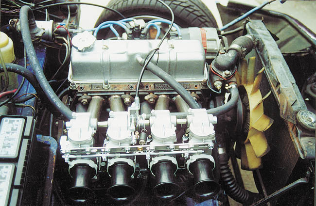
For the intake I am using a log-style manifold with a throttle body that is supplied by two superchargers. I have not heard the term IR manifold, but after a quick search, believe IR refers to individual runners. The intake runners are only 6" long and additional length would probably be beneficial. Although on my list of enhancements, the intake system is not at the top of the list. Nothing can happen until the engine has a cylinder head.frnkeore wrote: ↑Fri Oct 22, 2021 3:58 pm Now that I know the engine, valve size and rpm range (BTW, I had one of those engine, in a Jeep Wagon, many years ago), I would consider using IR manifold with Weber 40mm IDF or side draft 40mm DCOE carbs.
I'm a machinist, so I know surface finish. I would put a burr finish in the area, in the middle, between 125 & 250 but, it's not quite the same. Tool finishes are sharp and fairly, regular spaced. A burr makes radii marks, randomly spaced.
Regarding the transfer area, I'm sure it can be subjective, as to where it starts and ends but, for simplicity sake, let's call it from the center line of the valve (could be the back of the chamber, behind the valve, too), to where the roof of the chamber comes down to the deck of the block. In the post '36 Ford FH, with domed pistons, that would be, to the far side of the cyl. For the earlier engines, it's shape and extension, into the cyl varied, as shown in the attached pictures.
I'm a advocate of the FT piston, for FH's. Get the squish, as close as possible, say .036 and keep the roof of the transfer area, as low as possible, for the needed flow and try to keep the flow at a high velocity, with minimum turbulence. That's why I suggest a divider and a radius on the cyl. The larger the radius, the better, your probably limited to 3/8 there.
I think for your end result goal, you will need a flow bench, that you can mount a block on, especially if you could replace part of the cyl wall with plexiglass.
In the FH world, it take A LOT of effort, just to get near the 1 HP per C I area but, it is easier to do with the inline engines, over the V8's.
Yes, as a machinist, I would expect you to recognize surface finishes. However, I (and others with limited experience) need a cheat sheet (surface roughness comparator) to understand what an experienced journeyman is talking about. For example, if you say that you are looking at 63 Ra finish, I need to look at a sample in order to understand what you are looking at. Words like fast, slow, hot, cold mean little to me without a frame of reference (a measurement).
I agree with your thoughts on using flat top (I assume that is what FT refers to) pistons with a flat head engine. What I am seeing (strictly in a modeling world) is that the effects of squish is more effective (than a domed top pistion) with a flat top piston that has a negative deck clearance of at least 0.010 inch. The quench area is 37% of the piston area and the quench height is 0.042 inch. I can reduce that to 0.031" by replacing the 0.032" thick head gasket with one 0.031" thick. I am working with an existing engine design that has the piston 0.010" below the block deck.
With regard to the transfer area, you said "I'm sure it can be subjective." That brings me back the original intent of this post, what is it, where is it, how is it measured and how big should it be and why. This thread has been interesting and I have learned some new things - so that is good. However, I am going to start a new thread title "Flathead Combustion Chamber Transfer Area Defined & Measured." I am hoping that presenting my understanding of what it is and it's purpose will give readers the opportunity to call complete bulls**t on the idea, close but no cigar, maybe if the idea is tweaked a bit, or even, dead on!
Who do I talk to, or what do I do, to be able to post images rather than providing a link?

Re: Flathead Transition Area - What & where is it?
Ron Kelly a long time model A engine builder, built a new engine for his model A speedster for the annual national Model A hill climb held in Lincoln Nebraska every year. This engine was much the same as the rest of his performance A engines except that when he installed the new valve seats he installer then 1/8” above the deck. Did his regular valve job.
Upon starting and break in Ron found he needed to keep going richer on jets in the carburetor. I don’t know for sure but reliable sources say Ron went up 10/12 jet sizes.
What can be taken from this real would example is raising the the valve seat and valve 1/8” off the deck increased the air flow.
As Erland said if you want the skinny on flat head engine performance
Check out Jr Dragsters. They are close to 2 hp per cyl on flat heads.