Singh Groove testing redux and CFD for groove positioning.
Moderator: Team
-
- Expert
- Posts: 738
- Joined: Mon Nov 22, 2004 9:42 pm
- Location: ND
- Contact:
Singh Groove testing redux and CFD for groove positioning.
I have the chance (don't know about the energy though ) to do another dyno test of Singh grooves on a SB Mopar engine. I'm wondering if someone could run CFD analysis of the cylinder head groove since it seems to me groove placement so far has been a "best guess" approach, so I wonder if CFD run would help with groove placement.
Do you want the groove to stir up the hottest or coldest part of the chamber? Where does detonation start the hottest part of the chamber or the coldest? Or both?
If I do this test it would be very similar to that last one but with the addition of steady state tests, both WOT and part throttle, and at various RPMs to nail down more accurate BSFC numbers. One other thing I'd like to try is run the octane down to actual detonation without grooves to test if the grooves supress detonation on the dyno.
Further ideas or comments might be appreciated.
Some quick references;
To Detonate or not to Detonate ?????
pre-ignition / detonation(post ignition)
Quench "flame channels" in piston vs. head quench
Singh grooves in cylinder head
what do you guys think of this? (the long grooves thread)
Dodge 360 Grooves Testing, 2-17-06.
Jesse Lackman
http://www.revsearch.com
-
- Vendor
- Posts: 11003
- Joined: Mon Apr 11, 2005 2:30 am
- Location: CA
-
- Expert
- Posts: 738
- Joined: Mon Nov 22, 2004 9:42 pm
- Location: ND
- Contact:
The engine is 4.030 bore, 4.000 stroke, with iron RHS/Protopline 360-HPST heads, CR 10.8 without any chamber or piston dish work.
Here is a picture of a stock Magnum chamber. The RHS/Protopline 360-HPST chamber is very close if not exactly the same.
The first engine I tested grooves on had flat top pistons KB-107, these are right/left pistons with specific exhaust and intake valve reliefs.
The pistons in the second proposed test engine are a CP dished version, I don't have one available right now to take a picture. The dish does not match the chamber exactly so I was planning to do some chamber work to match the piston's dish and also to lower the CR some to help ensure it would run on pump gas.
How exact do you want to be?
=========================
One thing I'm wondering about is where the groove/grooves should be "aimed".
Theory (as I understand it) is that the grooves act both as mixing jet for the chamber and a fuse to light the quench area mixture.
So should there be one or more grooves?
Aimed at the sparkplug or intake/exhaust valves. or some combination of these?
If all the grooves accomplish is lower the octane requirement of the engine that alone is a big plus in a 90% street engine.
Jesse Lackman
http://www.revsearch.com
- Windsor377
- Expert
- Posts: 810
- Joined: Sat Apr 29, 2006 9:02 pm
- Location: Maryland
- Contact:
I found a tad better luck aiming the groove to the exhaust side of the plug. Split the middle of the heart and have the groove pointing to the threads on the exhaust side of the plug. Run it back to just short (0.040" or so) of the gasket. A single groove will show you some results you want. You shouldn't have to worry about lowering compression ratio either. Matching pistons to CC is a different issue, though.
Mike
Mike
Hello gents
THis does not relate specifically to the grooves...but in Mr. Widmers speedtalk lecture - he specified creating a pulse wave/squish and aiming it to the flame kernal( towards the spark plug area ). I beleive he does this on his "roller pistons?".
this interview was outstanding - anyone not owning it should get it. I dont know what it was about that CD .. but I just "got it"/understood it. Don thanks for suggesting it.
Jim
talon wrote:Hello gents
THis does not relate specifically to the grooves...but in Mr. Widmers speedtalk lecture - he specified creating a pulse wave/squish and aiming it to the flame kernal( towards the spark plug area ). I beleive he does this on his "roller pistons?".
this interview was outstanding - anyone not owning it should get it. I dont know what it was about that CD .. but I just "got it"/understood it. Don thanks for suggesting it.
Jim
I find it interesting, mpgmike talks of aiming a squish jet to the exhaust side of the plug and Larry Widmer describes a “pulse wave/squish and aiming it to the flame kernel”. Many photographs of the flame kernel in early stages show development at the exhaust side of the plug where many people consider to be an ideal location for flame growth.
I sent Larry a message maybe he will tune in?
Larry Widmer on PM wrote:There were a number of us who fooled with trenches and chamber/quench pad "fixes" in the late 70's and early 80's in some race programs that were well-financed enough to permit extensive dyno and track back-to-back testing. With the exception of some small improvements in RPM ranges far below anything we were running in competition, we saw no gains whatever...in fact, in most situations, we saw slight losses, even with lots of tuning time.
My thoughts on the grooves run something like this....if you have an engine that utilizes a relatively antiquated combustion chamber and piston design, it may help, especially in the lower RPM ranges, but don't expect to see them on our Honda's or other 4-valvers anytime soon!
Larry
Re: Singh Groove testing redux and CFD for groove positionin
Are you planning on grooving the heads or pistons,or both ?putztastics wrote:I have the chance (don't know about the energy though ) to do another dyno test of Singh grooves on a SB Mopar engine. I'm wondering if someone could run CFD analysis of the cylinder head groove since it seems to me groove placement so far has been a "best guess" approach, so I wonder if CFD run would help with groove placement.
Do you want the groove to stir up the hottest or coldest part of the chamber? Where does detonation start the hottest part of the chamber or the coldest? Or both?
If I do this test it would be very similar to that last one but with the addition of steady state tests, both WOT and part throttle, and at various RPMs to nail down more accurate BSFC numbers. One other thing I'd like to try is run the octane down to actual detonation without grooves to test if the grooves supress detonation on the dyno.
Further ideas or comments might be appreciated.
Please help make Speedtalk a Troll free zone.
-
- Expert
- Posts: 738
- Joined: Mon Nov 22, 2004 9:42 pm
- Location: ND
- Contact:
Grooves in the heads only, , what are you thinking??
I don't think I will have the energy to pull the heads more than one time, pulling the heads more than one time will run the testing into two days and I don't want to do that.
I'll be recording engine knock, I'm trying to get my son to build the setup to do that. I mean he's gonna get a bad case of blood clots from deep-dead butt thrombosis if I don't get him away from hours of dumb computer games.
I'm wondering if aiming the grooves directly at the plug is the wrong thing to do. I wonder if it can disrupt the flame kernel and travel, maybe that is why the grooves actually lost a bit of power in the higher RPM tests last time.
Jesse Lackman
http://www.revsearch.com
I was just thinking that pistons are cheaper then cylinder heads,
if you needed to undo the groove modification.
----------
If you were running(pick a number) let's say 30 degrees ignition advance,how far could the flame kernal develop before the quench effect
started to take place ? Probably a fair amount.
--------
I'd suggest starting your tests at as low an rpm as possible.
That might be where the "benefits" are seen.
Compare torque,and detonation resistance.
Please help make Speedtalk a Troll free zone.
-
- Expert
- Posts: 738
- Joined: Mon Nov 22, 2004 9:42 pm
- Location: ND
- Contact:
Here is an article by a guy who did a spectral analysis on the before and after grooves engine idle sound clips recorded during the grooves dyno test;
The Groovy Sounds of a 360 Magnum Engine
There are some CFD clips there too that are interesting.
The Groovy Sounds of a 360 Magnum Engine
There are some CFD clips there too that are interesting.
Jesse Lackman
http://www.revsearch.com
-
- Guru
- Posts: 1681
- Joined: Sun Aug 28, 2005 11:54 pm
- Location:
Going back to the original query regarding groove placement my approachputztastics wrote: I have the chance (don't know about the energy though:? ) to do another
dyno test of Singh grooves on a SB Mopar engine. I'm wondering if
someone could run CFD analysis of the cylinder head groove since it
seems to me groove placement so far has been a "best guess" approach,
so I wonder if CFD run would help with groove placement.
Do you want the groove to stir up the hottest or coldest part of the
chamber? Where does detonation start the hottest part of the chamber
or the coldest? Or both?.....
has been get as many possibilities that I can come up with out there and
see if I can figure out what works best.
Most of my experience has been with the single groove pointing at the
plug. This has work out very well with no problems encountered. I have
over thirty engines running with this layout including N/A, NOs and blown
applications. My thoughts on pointing the “jet” at the plug is IF the jet
forms a concentrated stream that reaches the plug it does so too late in
the cycle to quench the flame kernel. I make this conclusion because with
the engines I have done all have reduced misfire tendencies.
Several of the EFI engines I did with a single groove were tuned on a
chassis dyno. I suggested reduced ignition advance thinking the
requirements would be less than normal. In all cases the engine lost power
with less ignition advance. Much to my surprise with 2 degrees more
advance than normal for these engines an additional 20 -25 RWHP was
recorded. I can only guess these engines normally run on a knock sensor
and the modification allowed more advance? Two of these engines have a
more modern LSx combustion chamber.
With NHRA’s relaxed rules on combustion chamber modification several
Super Stock racers have approached me about the modification. I had a
long discussion with Wesley Roberson, division four tech. His response
was they would change the configuration of the chamber making them
illegal.
I did several engines with a multiple parallel grove layout. The engines are
performing well, I can’t say if this is an improvement, perhaps more time
will tell.
Lately I have been trying “converging grooves”. This idea was the thinking
of “Silverback” from the Maryland area. First indications are good but
more time is needed to determine if this provides additional benefits.
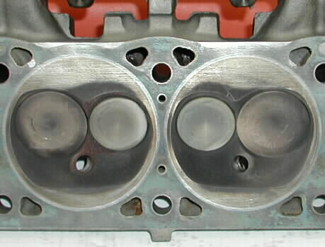
Here are three basic layouts I use for the wedge head:
- Windsor377
- Expert
- Posts: 810
- Joined: Sat Apr 29, 2006 9:02 pm
- Location: Maryland
- Contact: